Category
This project is about Automatic Changeover Switch Using IC. Sometimes due to power failure, our home appliances burnt or our work stopped badly. To overcome this problem we have to use alternate power to continue our work without any hesitation. We use UPS batteries or generators as alternate power supplies. If we change our power manually it's a big problem for us. The main function of the Automatic Changeover Switch is to change the power automatically from UPS to main and main to UPS. The given circuit diagram shown here is of an automatic changeover switch using IC LTC4412. This circuit is used for the automatic switchover of a load between a battery and an adapter.
circuit diagram of the automatic changeover switch is given below with total parts detail. You can modify this according to your need.
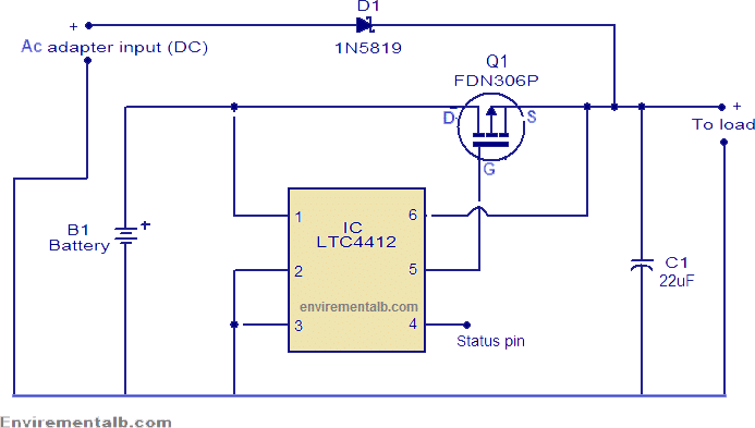
IC LTC4412 controls FDN306P P-channel MOSFET to create a near-ideal diode function for power switchover and load sharing. This makes the LT4412 an ideal replacement for power supply OR-ing diodes. IC LTC4412 gives much flexibility in terms of load current. LT4412 also has also good features like reverse battery protection, manual control input, MOSFET gate protection clamp, etc.
The D1 (Diod) prevents the current flow reverse to the adapter when there is no mains supply. The C1 capacitor is the output filter capacitor. Pin 4 of the IC is the status output. When the main input is present the status output pin will be high. The output of Pin4 can be used to control another P-channel MOSFET if needed.
In this changeover switch, we have used a simple relay to control the changeover with the 12v adopter. The working of this Line changer Circuit is very simple and easy to understand. When current is present in both lines then Line 2 is in an active state because the coil of both relays is connected with line 2. As line 2 power shutdown 12v adaptor current was cut off and the relay was turned off and both relays connected with line 1.
A wide variety of relays are available in the market but we have used very simple and basic relays in this automatic changeover switch circuit. These types of really are available in almost all home appliances like the stabilizer, electric boards, washing machines and etc.

I hope that this basic and useful automatic changeover switch will be very interesting and informative for you. If you have any doubt or question about any electronics circuit you can free contact us.