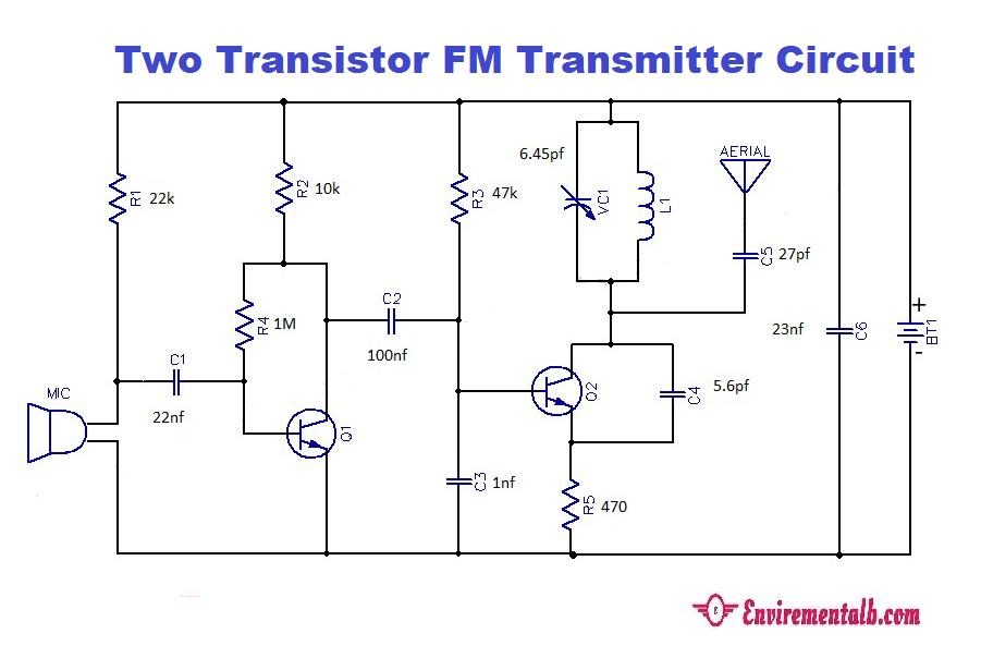
In a previous post, I made one transistor FM Transmitter that is also very nice and easy to make. This is just another one, two transistor FM transmitters. It has two stages. The first stage amplifies the audio signal, generating a carrier signal using an oscillating, and the second stage modulates the carrier signal with the amplified audio signal. The amplification is done by an amplifier, whereas the modulation and carrier signal generation is done by a variable frequency oscillator circuit. Frequency can be set at anywhere between the FM frequency range from 88MHz to 108MHz. The power of the FM signal from the oscillator is then amplified using a power amplifier to produce a low impedance output, matching that with the antenna.
Two Transistor
Application of FM Transmitter Circuit
list of components
| 1 |
10k |
R1,R4 |
| 2 |
1M |
R2 |
| 3 |
100k |
R3,R5 |
| 4 |
0.1uF |
C1 |
| 5 |
4.7pF |
C5 |
| 6 |
EMP |
U1 |
| 7 |
2n2222A |
Q1,Q3 |
| 9 |
ANTENA |
U2 |
PCB For circuit
Notes.
- The circuit can be powered from anything between 6 to 12V DC.
- Noise can be eliminated with the use of the battery.
- If you are going with a battery eliminator, then it must be well-filtered and regulated.
- The antenna can be a 1m copper wire.
- L1 can be constructed by making 4 turns of 1mm enameled copper wire on a 10mm diameter plastic former.
- Most of the components required for this circuit can be taken from old circuits.
- The range can be increased with a high antenna and power full battery.
- A list of all components is also given on the circuit diagram.

Application of FM Transmitter Circuit
- FM Transmitter circuits are used in a sound system.
- These are used in wireless components used in vehicles and offices.
- The circuits are used to make FM transmitters used to reduce the noise in important places.
Advantages of FM Transmitter Circuit
- The FM Transmitter Circuit could be made very easily as the very common components are used.
- Above circuit gives a very high efficiency in transmitting signal.
- The circuit is best suited for demonstration and FM transmitter circuit projects.
- The circuit does have large and complicated components.
- The transmitter circuit is capable to neglect the noise signal through the amplitude variation.
Disadvantages of FM Transmitter Circuit
- In the above FM Transmitter Circuit, there is a large wider channel needed.
- With the Circuit, the transmitter as well as the receiver tends to become more difficult.
- The received signal gets poor quality as there interference occurs in the medium.
- The above circuit is not good enough for high-power FM transmitter circuit purposes.
Advertisements